
DK7ZB claim, false? DK7ZB Wrong
11 Jul 2012
DK7ZB undermining attempts continued 10/9/2012
For the original post you will look to the bottom of this page but it seems our friend Martin, DK7ZB has really had his noise put out of joint now but why has he reacted this way and to what? He has set about trying to discredit me and the LFA Yagi but for what reason? Is it the fact that he feels I have undermined his work with my designs being so much better than his?
The fact is, with YO or (Yagi Optimiser, used by DK7ZB) antennas that can be produced within a few minutes. Within this software you can select the number of elements you wish to use, an aproximate length of boom and press go (you need very little knowledge about Yagis and adjustment parameters at all to use it). A few minutes later, you have a Yagi. Not a good one, but you have a Yagi. As with many amateur designers, Martin makes the 'gain, gain, gain' mistake and has simply optimised for maximum gain without regard for pattern, side lobes (in particular the elvation plane) or bandwidth. Any of his antennas that have some kind of bandwidth seem to have been 'luck hits' and those with seemingly good F/B have HUGE, uncontrolled elevation lobes as a byproduct.
Some tips for Martin:
Optimise in the elevation plan only. It is clear to see you optimise in the azimuth plane as almost always your elevation plots are 'blown'. Optimising in the elevation plane will result in the azimuth plane looking after itself, this dose not work in reverse. Optimising in the elevation plane will also result is flatter performance curves is all areas and will help control bandwidth.
Use 1 degree steps, using 5 degree spacing allows for odd lobes to appear between the steps, especially at UHF.
Fix your first and last element positions in order the optimiser has to search for the best results between those points.
If with fixed first and last elements the F/B is not good enough, shorten the boom slightly and optimise again. It takes longer than 5 minutes in YO but you get far superior results.
These points are free, mail me and I may give you some more hints to make your antennas better :-)
Joking aside, YU7EF antennas have alwasy been far superior to the DK7ZB YO designs. However, while Pop has a good comand of the English language, he has perhaps not been best placed to communicate what makes a good yagi good. I know from speaking with him that he has chosen not to write on the subject too much. The importance of flat-line impedance curves, flat bandwidth and flat performance (performance meaning gain and F/B) when hams have searched for a Yagi design, are overlooked. They look at number of elements versus gain and decide upon an antenna that way, that's it. Despite the fact they cannot use it in rain and snow and get huge static noise comes after they have built it. The fact is, per foot or per metre of boom, the gain figures on the YU7EF antenna are very similar and yet they offer so many more benefits including the ability to hear much better.
The difference between Pop and I was that I was able communicate what makes my antennas different more easily and applied lateral thinking to my designs. Martin points out in his latest rant that the LFA is nothing more than a 12.5 Ohm antenna with a loop on it. Congratulations, well done. This is exactly the communication I have made in my aticles, the fact that if an antenna is designed right, it need not be anything other than 50Ohm and lower impedance antennas are best when the driven element is arranged so as it is 50Ohm. The OWL is a 12.5Ohm antenna with a folded dipole, this makes for a 50Ohm direct feed Yagi. The LFA can be anything between 6 and 20 Ohm (if a split dipole is used instead of the loop) and the LFA loop is adjusted (in both X and Y planes) to create the impedance trasnformation to 50Ohm. The OP-DES Yagi uses bent back tips at the ends of the driven element to raise the impedance for 50ohm (first used by UA9TC on his reflectors), this indeed was the target.
To Martin's untrained eye, he sees 'nothing more than a 12.5Ohm Yagi'. The fact is, this 12.5Ohm Yagi as he calls it, has a driven element which is high impedance and requires no matching arrangement at all. unlike his rain-shifting, narrow band 12.5Ohm Yagis, the LFA is stable and provides performance over wide bandwidths. It also has a closed loop providing all the benefits that brings in terms of noise. The fact that his 12.5Ohm Yagis are extremely narrow band demonstrates again the lack of understanding of his tools and the products which it produces. He has allowed his optimiser to take the easy route to gain which is extending boom length to a point where the elements are too far apart to provide any form of stability.
In one of my earlier DUBUS articles, I discussed the fact that if designed right, a low impedance Yagi can provide much wider band performance than an OWA Yagi. I discussed an experiment where I optimised an OWA (50Ohm dipole fed Yagi) for maximum bandwidth with at least 20dB F/B. When I re-optimised with a 40Ohm feed point impedance, I could achieve wider bandwidth with more gain and better F/B, proving the lower the impedance, the better it could be in addition to having the potential to provide performance over much wider bandwidth than a comparable OWA. However, until now no one had taken advantage of the far superior performance that could be achieved from lower impedance antennas.
The issue for me was the matching arrangement, placement of a matching device in the antenna can have detrimental effects on pattern and performance and therefore, the objective of producing a driven element that could provide a Yagi that would otherwise be low impedance if a split dipole feed was used.
In Martin's original post he made these comments for the reason an 'LFA' was beign used in the WWII 'Due the problems with the allied blockades of the system they needed a broadband yagi with high directivity for frequency changing'
This demonstrates a lack of understanding of Yagi design (along with confirming the reliance of the simplicity of YO) as the loop does not make the LFA broadband. Careful optimisation and an understanding of the subject in hand is what produces a broad band Yagi antenna. Allowing an optimiser to run away with boom length, ever increasing the spacing between elements (which is the easy route to gain and the cause of your antennas instability) is why in general (although there are a few exceptions) the DK7ZB antennas are the way they are (12.5Ohm in particular).
From his comments, it is not clear if Martin really has an understanding of the difference between a 12.5 Ohm antenna and a 50Ohm antenna so for you (and him) I will explain through pictures and text.
If you have a low impedance dipole fed Yagi, and install some form of matching device, the driven element is still low impedance and hence, high current. There are issues with low impedance driven elements such as higher noise pick up and high current across joins and connections which can lead to problems in QRO enviroments.
OK let us look at a 12.5Ohm OWL antenna below
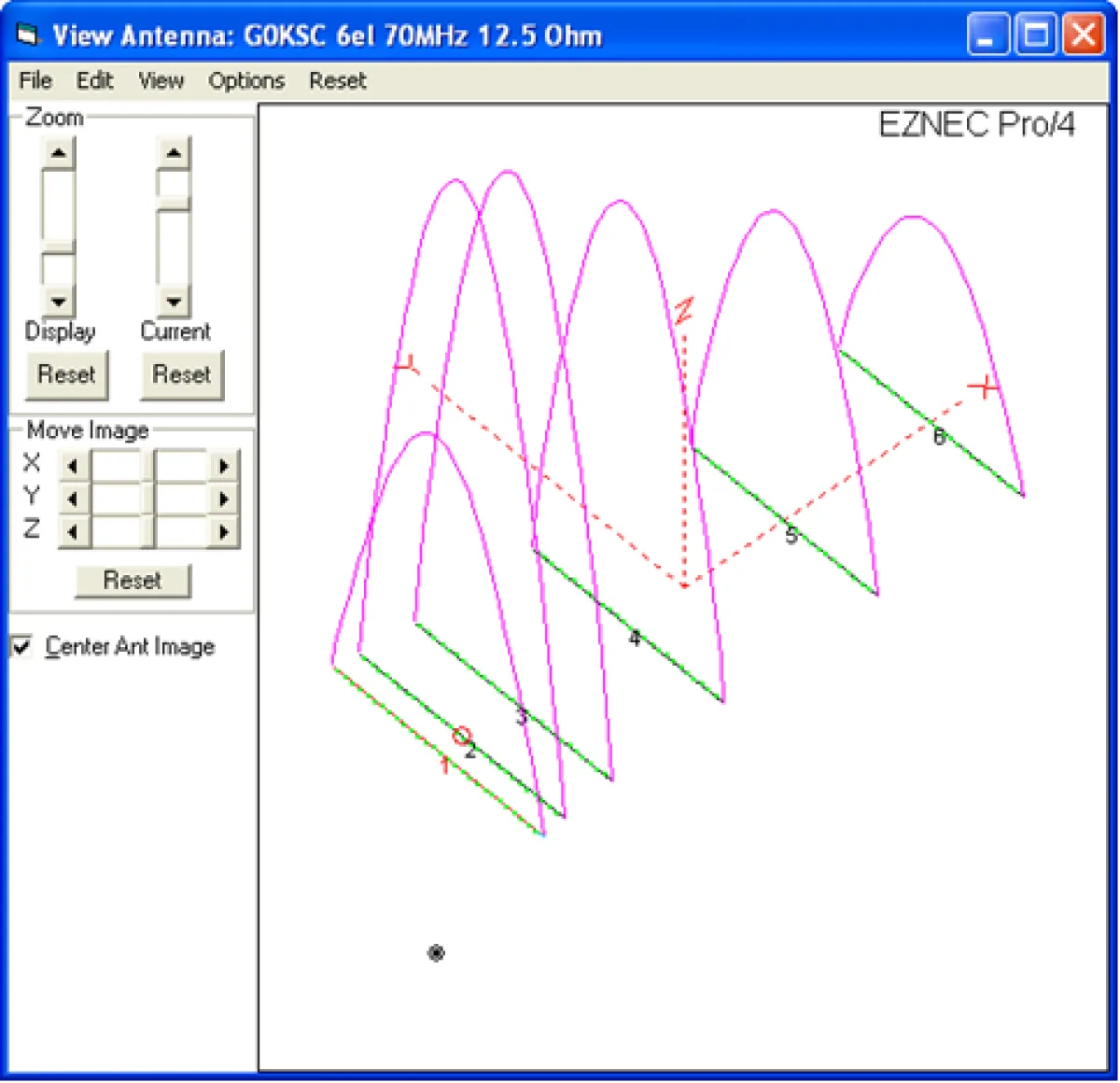
The above is a 12.5Ohm dipole fed Yagi of my own design The green lines are the elements, the pink curved lines represent current distribution throughout the elements. We can tell this is a low impedance antenna as the current distribution is high within the driven element. Now let us take a look at the same antenna fitted with a folded dipole.
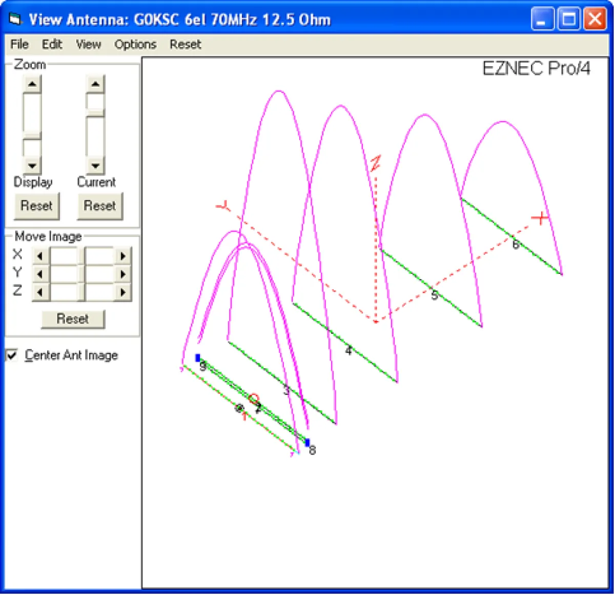
All that has changed in this exampe is a folded dipole has replaced the split dipole. Notice the current curve? It is much lower as the radiating element is now HIGH IMPEDANCE, this is now a 50Ohm antenna and this carries with it all associated benefits. It is simple isn't it? The fact that the drive element is also its own matching device means the entire antenna (as it will be built) can be modelled without having a nasty low impedance split dipole the other side of any matching device. The LFA is the same and so too is the OP-DES.
As an example, below is a correctly modelled 12.5Ohm Yagi usign a split dipole. This is a 14el 144MHz of my own design:
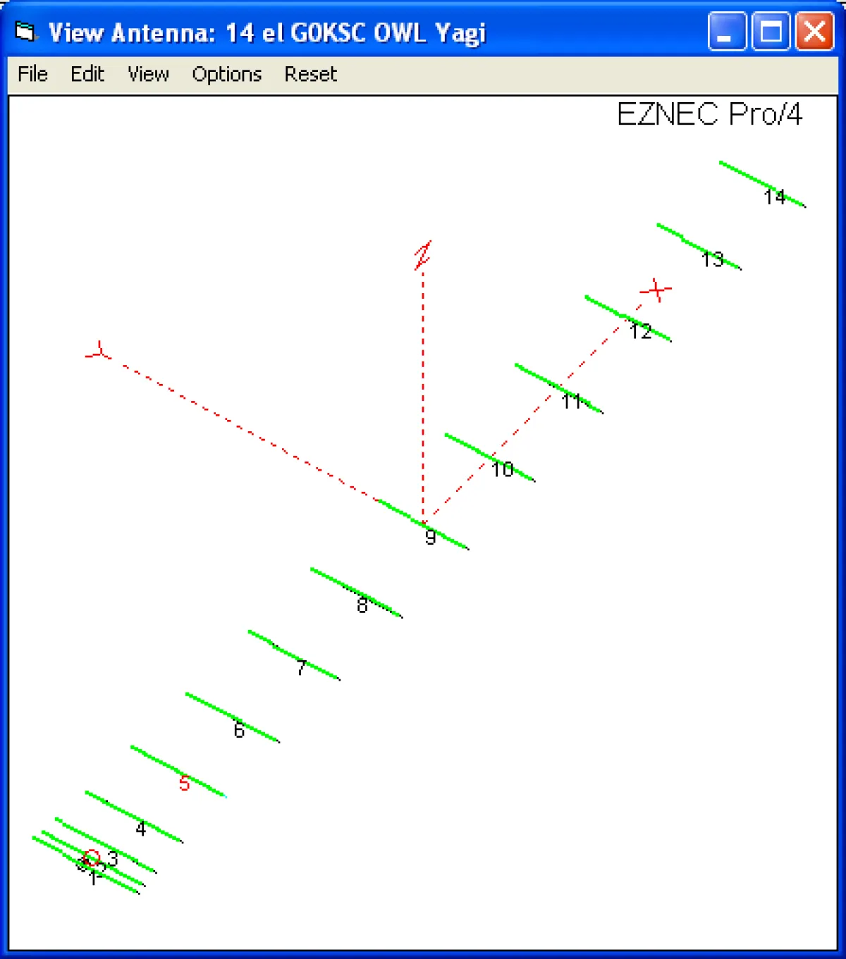
Note how very close the first few elements are together? This is something you would simply not achieve with an optimiser that was allowed to extend its boom size. The lower the impedance a Yagi is, the lower this 'driver cell' has to be in order to achieve stability. Now let us look at SWR:
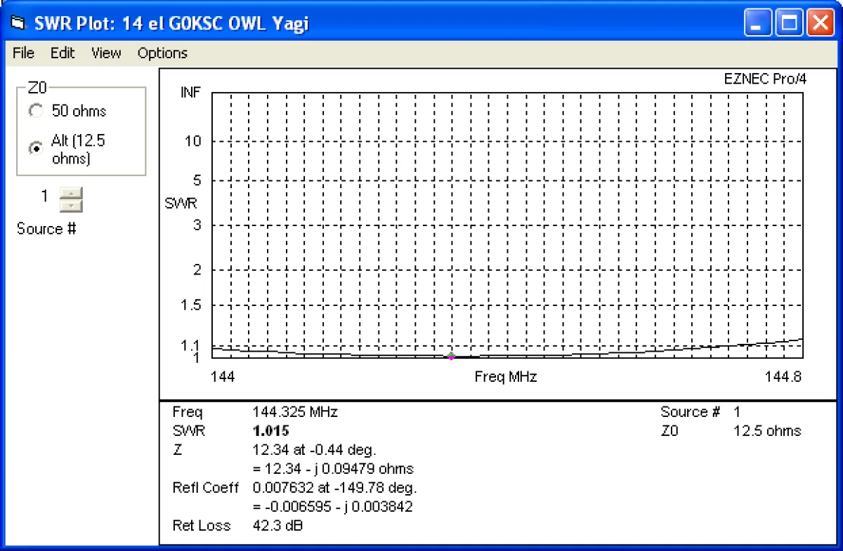
Note the 'Ski Slope' Impedance curve and V shaped SWR that a 12.5Ohm Yagi has becoem known for is not there. This antenna provides a broad, flat impedance curve across a wide range and as a result, maintains sky temperature and G/T across a wide range too. Next lets take a look at how the plots of a correctly optimiser 12.5Ohm Yagi should look:
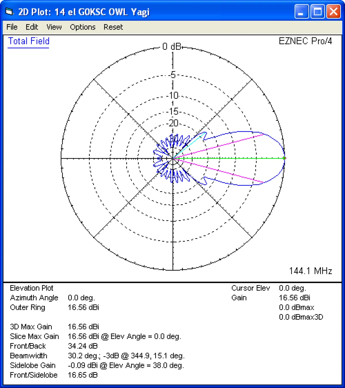
This is not an Azimuth plot, this is an elevation plot. Note the near-perfect symmetry at the back of the antenna and the huge reduction in lobes after the 45 degree line and back? This is how a Yagi should look, not with huge side lobes straight up and down which pick up large amounts of noise from your surroundings. Now the Azimuth plot:
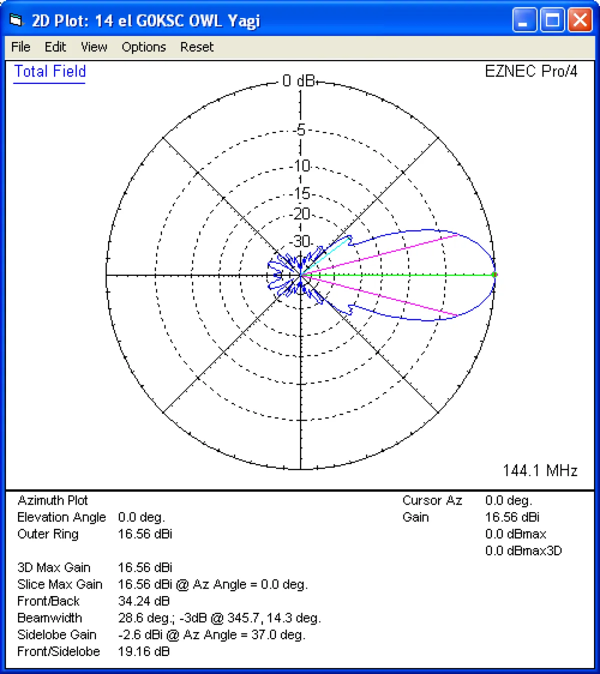
Good levels of suppression to the sides, virtually no side lobes to speak of and excellent F/B but this is at 144.100MHZ right? How does it look at 144.300MHz?
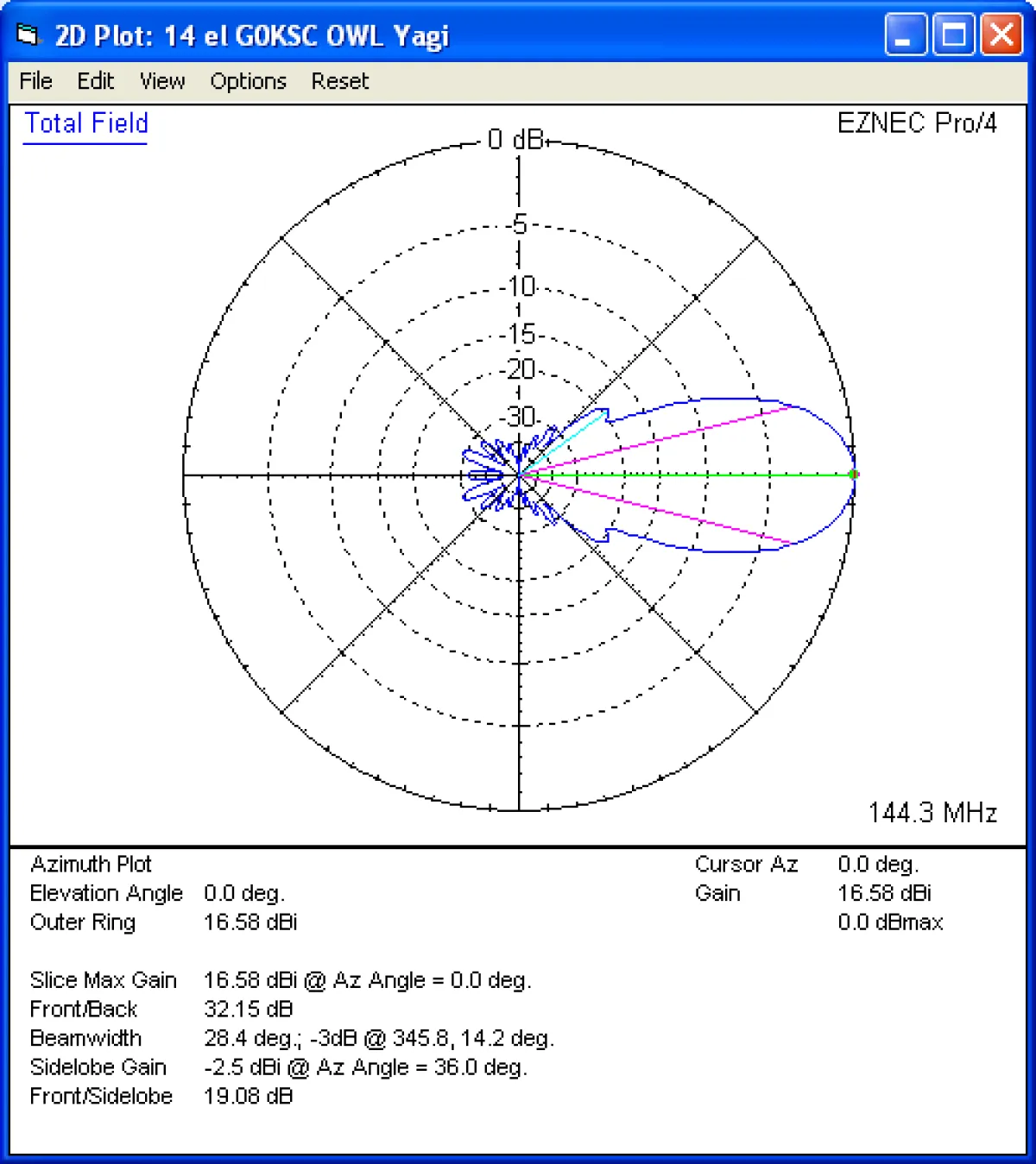
Virtually exactly the same at 144.300MHz as it was at 144.100MHz this means Sky temperature and G/T are maintained. Now 144.600MHz?
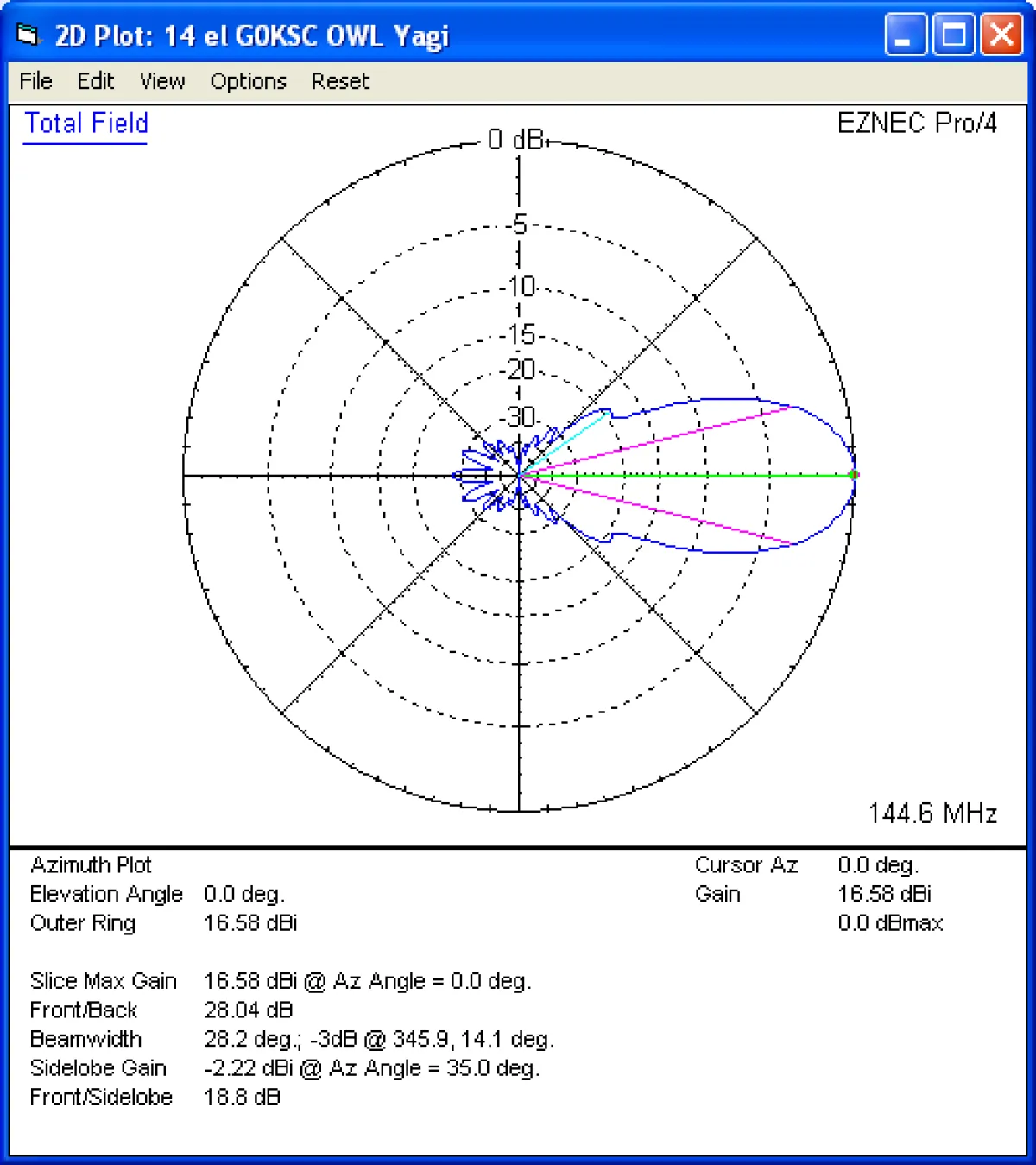
Starting to see a small drop in F/B by 144.600MHZ but gain , side lobes, and side suppression all maintained is in summary, building this antenna would ensure you get model performance, even if you were a littls out and the antenna were shifted from model simply because it is so wide.
You simply cannot desing every antenna of ever impedance for every band in the same way, many considerations have to be taken into account. Designing VHF and UHF Yagis in the same way as you would HF Yagis does not yeild good results. The above example is how a 144MHz Yagi should look. Additionally, IF DESIGNED CORRECTLY, A YAGI NEVER NEEDS TO BE ANYTHING OTHER THAN A DIRECT 50OHM FEED. Add a folded dipole to this antenna, a small amount of reoptimisation and you are good to go with the best antenna available at this boom length, period.
Now go have a look at Martin's site and some of the plots, which would you rather have on your tower?
As much as I know it must pain Martin so much, the LFA is not a folded dipole laid flat on the boom. Below is another plot from EZNEC showing current distribution, this time on an LFA.
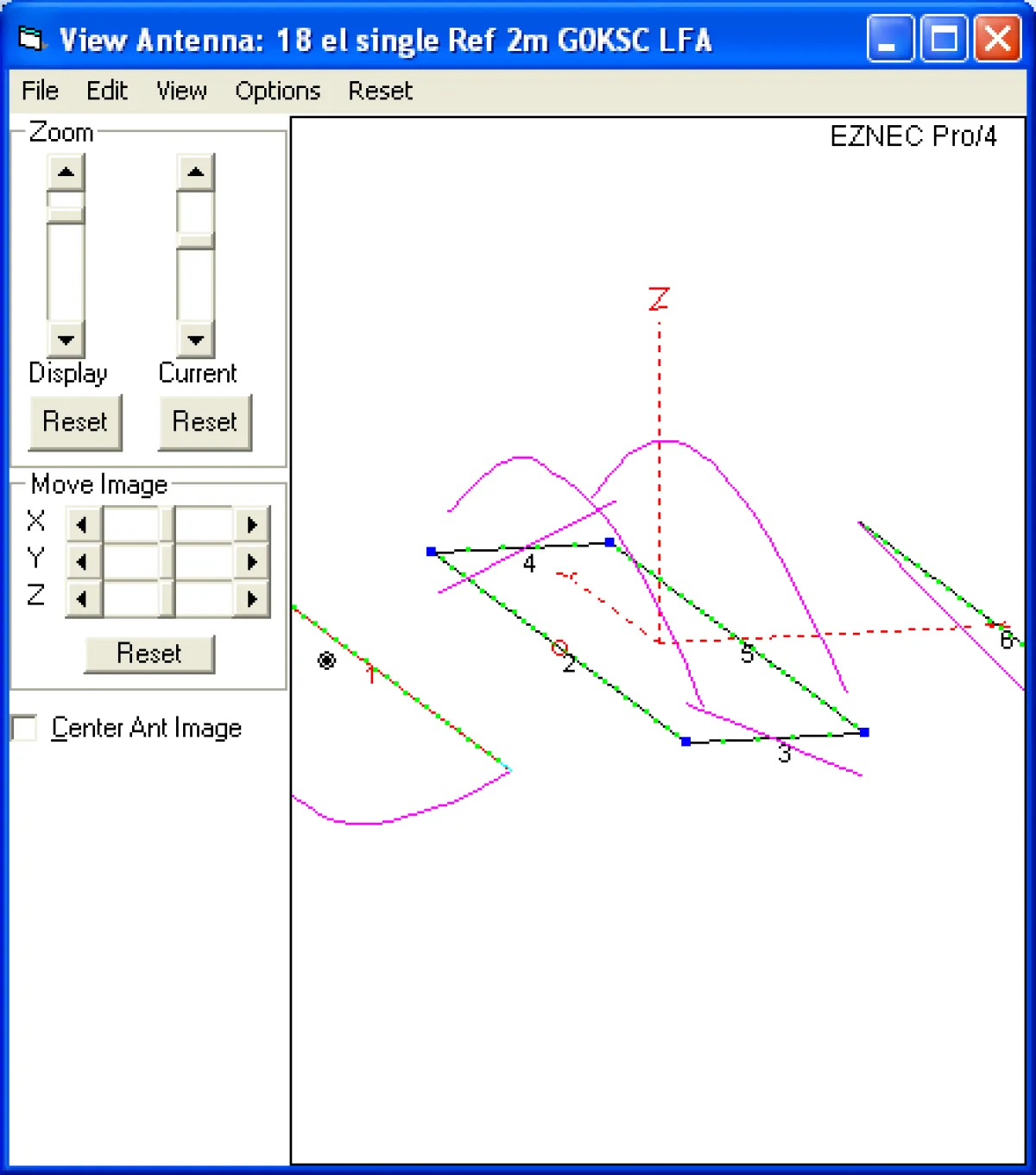
This is a side view of the LFA loop. It is not a folded dipole, it is a rectangular, flat sided loop. The loop sections are numbered above. You have 2 and 5 which are the longer front and back sections of the loop and 4 and 3 which are the side sections. Rather than just show current distribution in this plot, EZNEC is enabled to show current phase angles too. Therefore, the angle that the pink lines move away from the element section is representative of the phase angle. Note that the two side sections of the loop (which are flat, not rounded like a folded dipole) have pink lines runing in opposite directions from one another. This is because these two side sections are 180 degrees out of phase. This is has cancellation effect (as you would see on balanced line feeders) and therefore, if careful optimisation take place, this can be used to increase suppression off the sides of the antenna and increase front to back ratio too.
Martin's attempts of undermining this time extend to the use of other sites to where the authors have spent little time investigating and comparing antennas other that at the highest level. see an example here:
The author reverse engineers an 8 element element LFA to produce a spit dipole antenna of 12.5Ohm which does not have the same suppression in the rear lobes as the original so while he does not mention it, he had proven the loop concept is better. He also fails to mention the issues and losses associated with maintaining a 12.5Ohm dipole and any associated matching devices they may need to be added. Finally the author displays a number of TV antennas displaying FOLDED DIPOLE driven elements.
Finally, I have until now only produced and presented a few 28Ohm Yagi antennas. One in particular, a 17 element 144MHz antenna which I fitted with a folded dipole was preented in DUBUS magazine. Although the original dipole was 28Ohm and not 12.5ohm there is reason for so doing. The original DK7ZB coaxial dipole connection involves joining in parrallel 2 x 75Ohm pieces of coax. This is messy at best and hard to achieve without additional unwanted losses. However, with the new 112Ohm folded dipole, a single piece of 75Ohm coax (1/4 wave length) can be used with a simple N type connection on the oppsite end for connection to any 50Ohm feed line. This antenna can be found on the VE7BQH list:
http://www.dxmaps.com/VE7BQH.html
If you are not a subscriber to DUBUS magazine, you would have missed this antenna but scroll down the list at the above link to '+G0KSC 17OWL-FD'
Now take a look at the performance. Note, it has more gain, much lower sky temperature and a much bigger G/T figure than not just Martin's antennas but of anything else of that length. This is in addition to having an SWR of better that 1.1:1 across at least 1MHz of bandwidth and therefore, very stable. Note in particular the G/T figure. This is a mean opinion score between antenna temperature and antenna gain which demonstrates the antennas ability to receive weak signals. The more positive the number, the better and my 28Ohm antenna has a G/T of +0.33dB. Take a minute to scan up and down the list and note how far away from everything else this antenna is. I guess when you see the space I have opened up, it is kind of understandable why he has such a cobb on right? :-)
How was this achieved? Well, the 28Ohm feed impedance is a great point of balance for gaining best performance in all areas but just until now, no one with any modelling ability has taken advantage of antennas using a split dipole feed of this impdedance.
Therefore, while I am not a fan of the twin line 75Ohm coaxial matching transformer and much prefer to have a self matching driven element, I will now produce and publish a range of 28Ohm antennas that are modelled as they should be. They will provide a very wide and stable performance in all areas including Gain, F/B and SWR. The small selection currently linked on G0KSC are early, 'concept' designs. The new line of 28Ohm Yagis will aim to set new standards as all my antennas do.
So, Watch this space, the best in 28Ohm Yagi performance is about to arrive!
ORIGINAL POSTING BELOW
DK7ZB claims on his website that the LFA (Loop Fed Array) concept was first discovered by a German professor in the second world war for use as a radar antenna upon air planes. This he has published upon his news page (the full passage can be read towards to bottom of this page below).
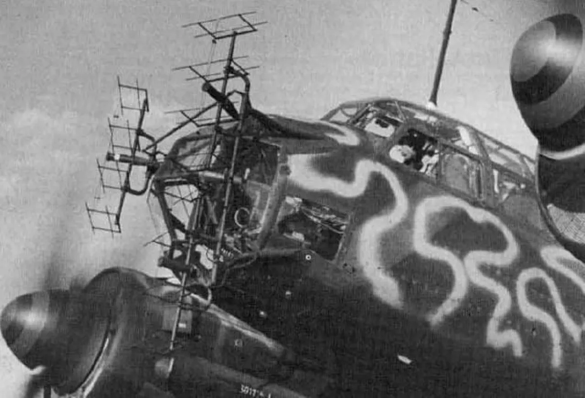
I decided to search on Google for 'FuG200' or 'Hohentwiel' and other variants I could think of. I searched the images section of Google to see what I could find because there should be a vast number of different planes with these antennas on them right? For me (and anyone else I have asked to search), all I found was many photos of different planes sporting Yagis at the front of them but all have traditional 2 or 3 element Yagi arrays, the only one on the Internet with the loop section at the back is the one DK7ZB has on his site!
Lets face it, even if this antenna is real (blowing the image up in photoshop suggests otherwise) and has a rectangular loop, it is hardly an LFA Yagi by G0KSC is it? An LFA Yagi has a driven loop and half wave parasitic elements either side of it. It has a direct 50Ohm feed point and is optimised in order the ends of the loop are 180 degrees out of phase with one another which helps reduce side lobes in both the elevation and azimuth plane; no Huge sidelobes only 15dB down. This optimisation is done while maintaining an extremely flat impedance curve over a wide bandwidth and requires no matching device of any kind.
In modern times, we know that a Yagi does not need to be anything other than 50Ohm direct feed if it is modelled correctly. Powerful software enables us to achieve this with ease these days, we do not have to put up with matching losses, power limits, pattern distortion or any other of the negatives that come from Yagis with an input impedance of anything other than 50 Ohm.
LOL, hats off to you Martin, nice try but I think you have simply undermined yourself rather than undermining me! No need to feel threatened by me my friend :-)
Martin's post:
| In the last time you read a lot about the interesting LFA-Yagis by G0KSC, who claims the invention of this "new" antenna type.
But the credit goes to the German Airforce in WW2! A development group around Prof. Scherzer invented the LFA-Yagi about 70 years ago for the famous Radar FuG200 "Hohentwiel"! Due the problems with the allied blockades of the system they needed a broadband yagi with high directivity for frequency changing. The name of the antenna was "Zaunkönig" because the whistling noise during the flight remembers a bird... The photo from 1942 shows the early antenna type mounted on a German nightfighter He-111. Mni tnx to Carl, SM6HYG for this interesting information! |
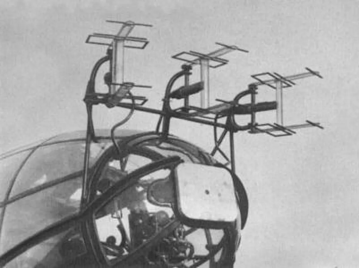
Photoshop at its best - The image DK7ZB displays on his site of the first 'LFA' Yagi
Some photos of the real FuG200 radar arrays can be seen below:
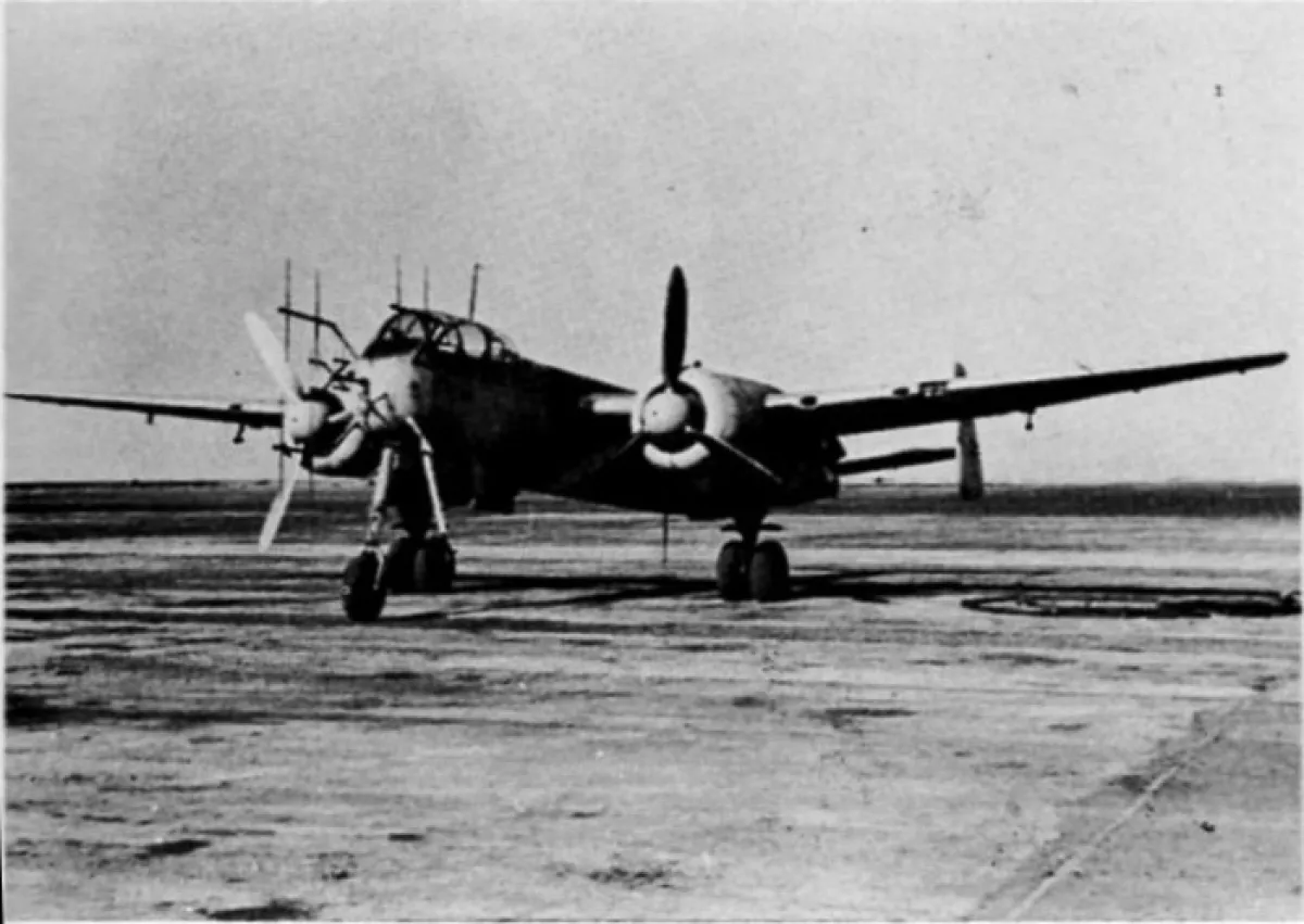

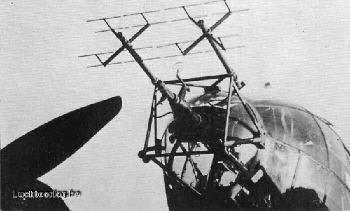
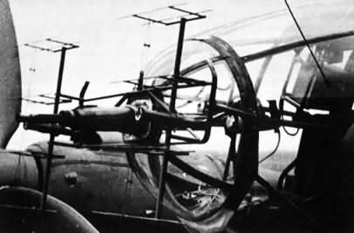
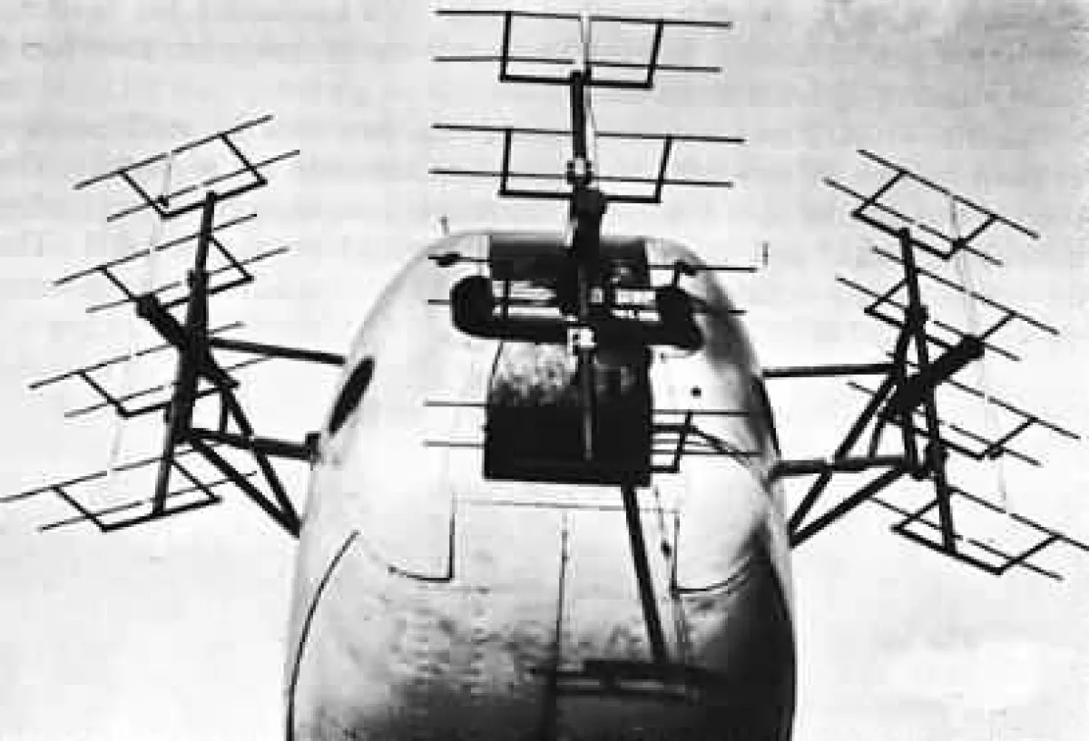
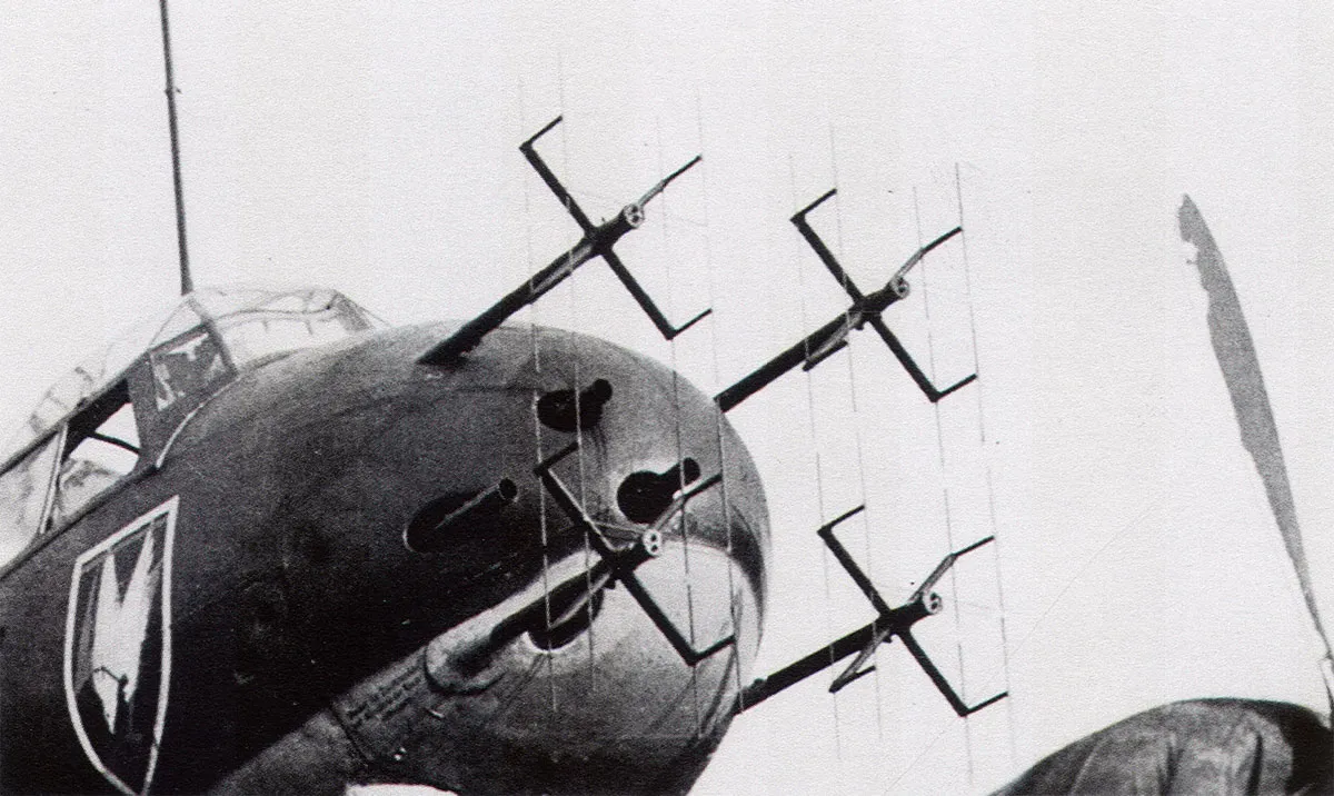
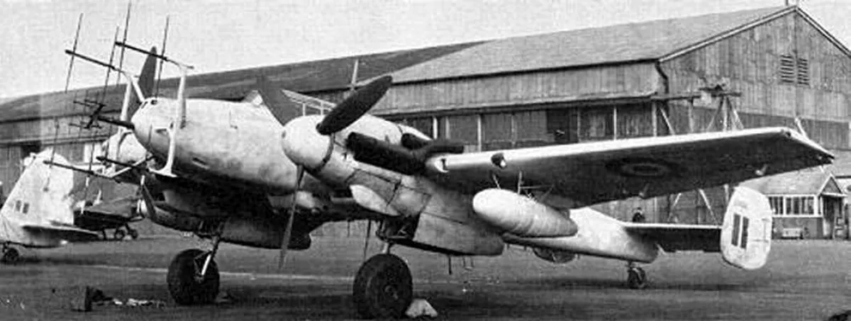

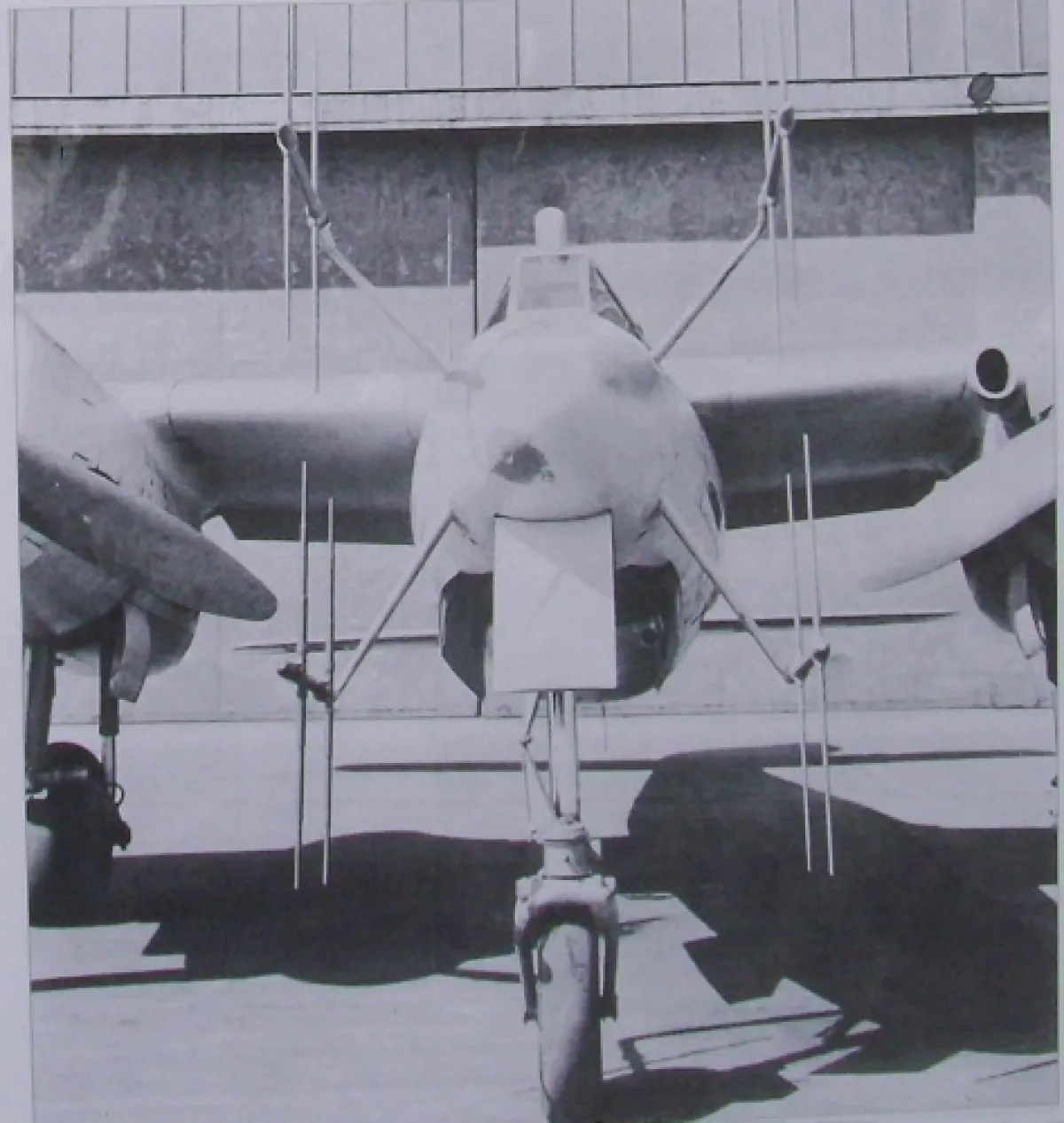
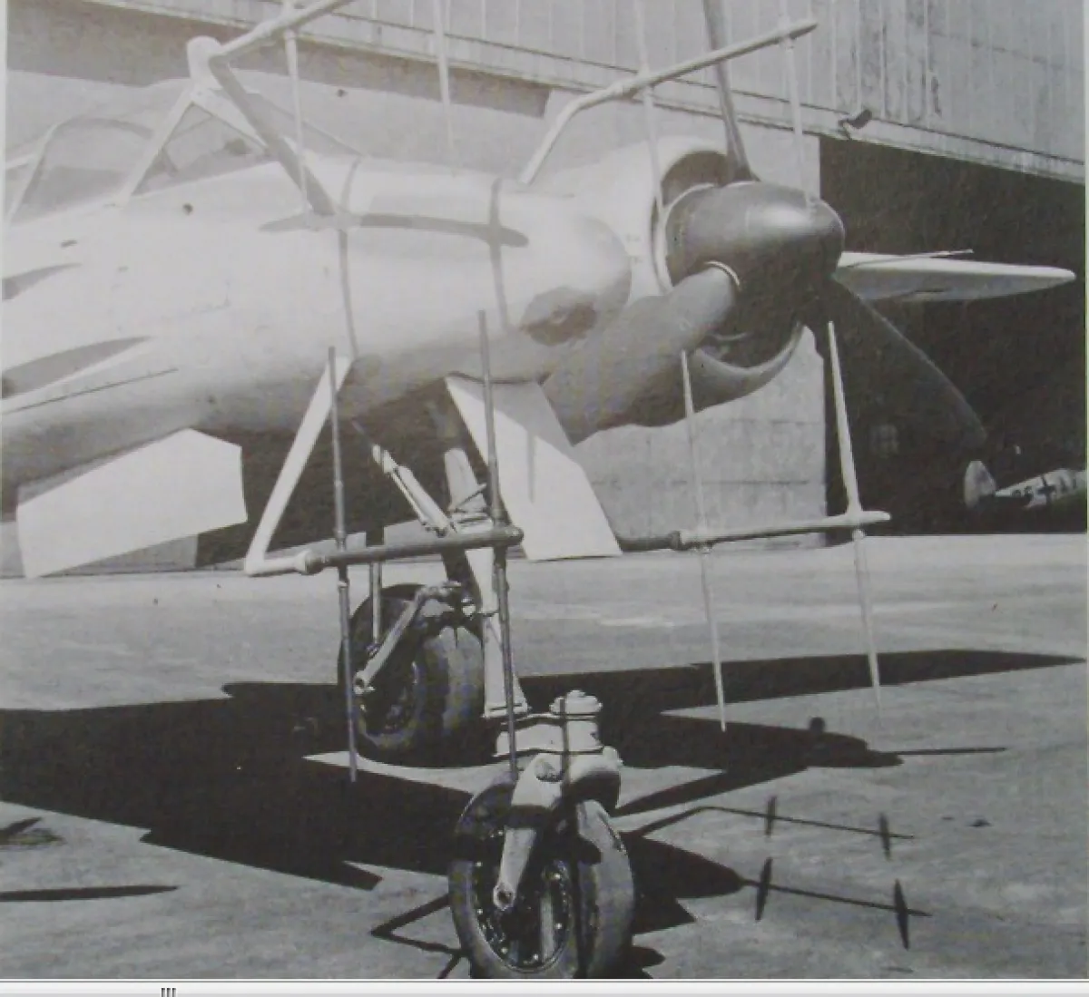
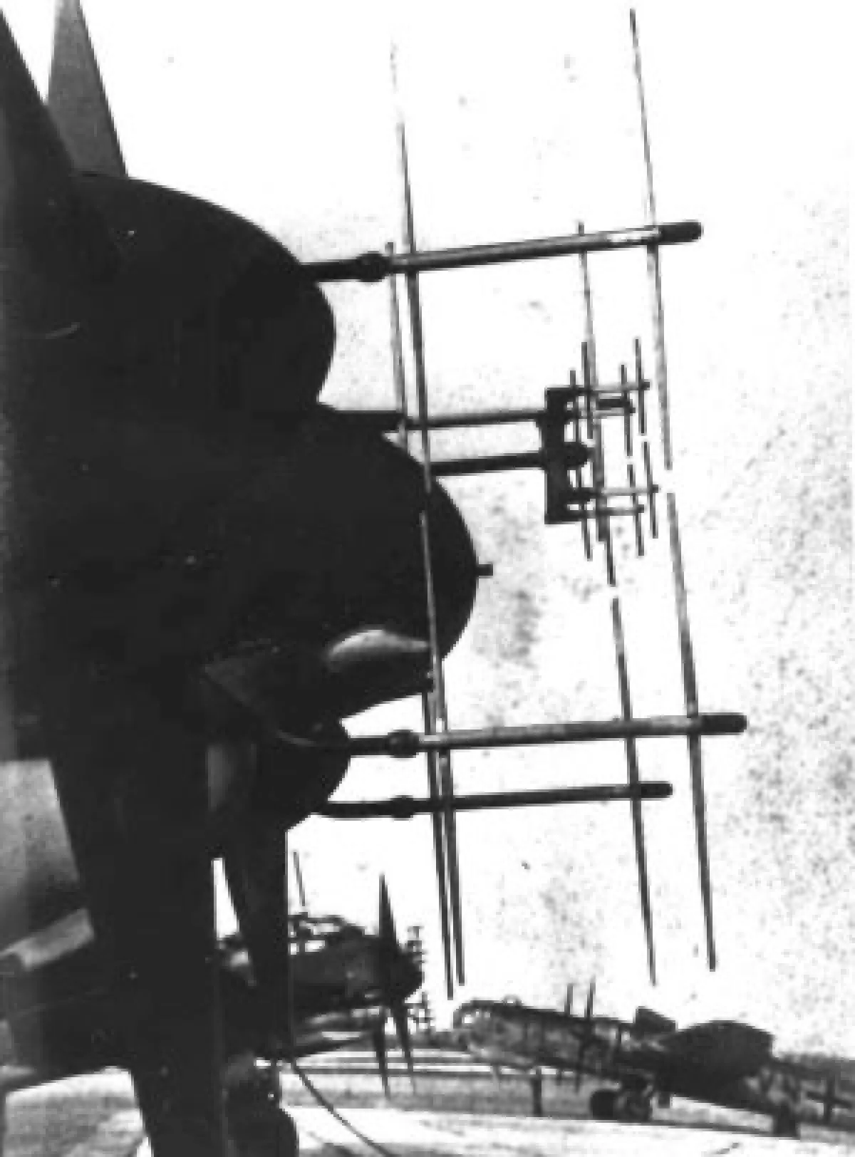
Finally, some WW2 replica models with the 'real' FuG200 array installed
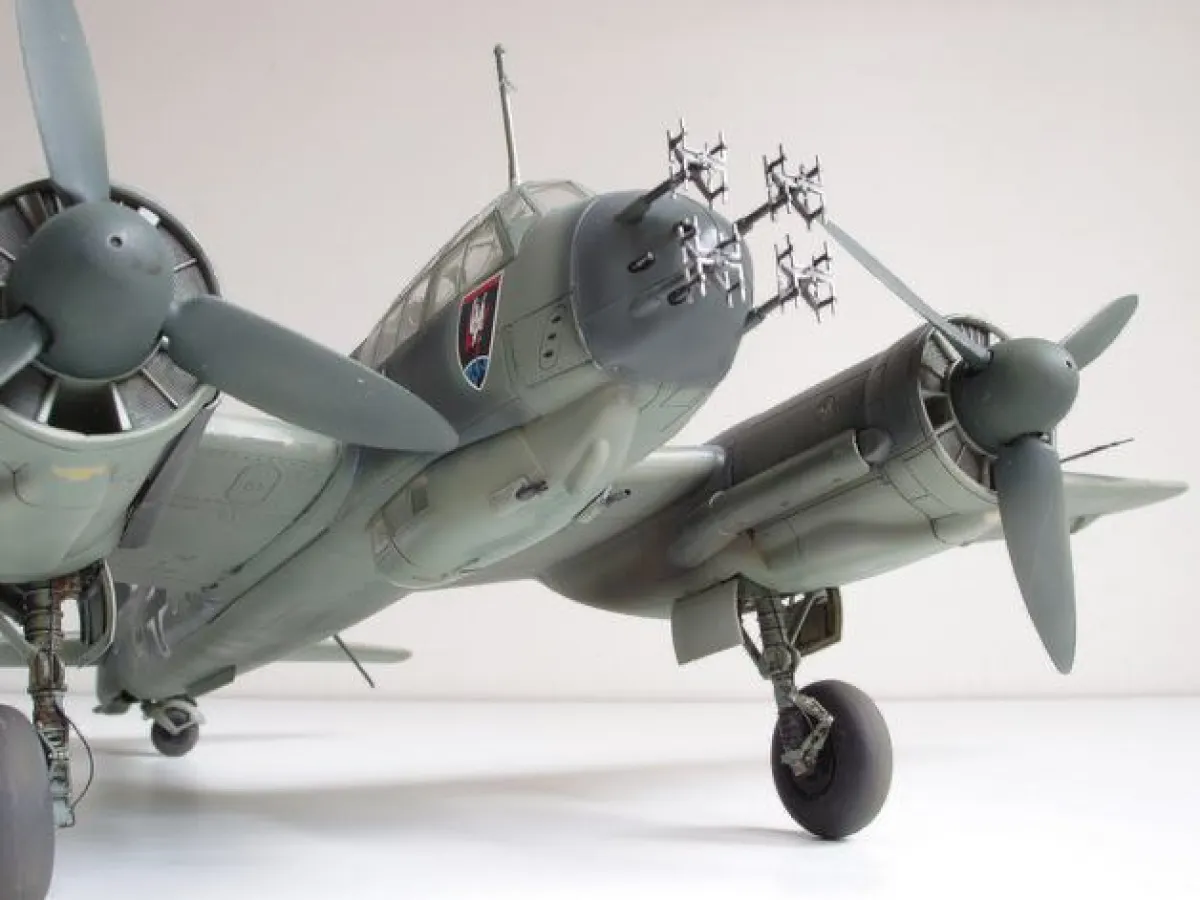
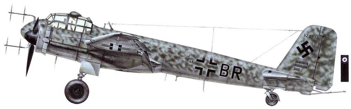
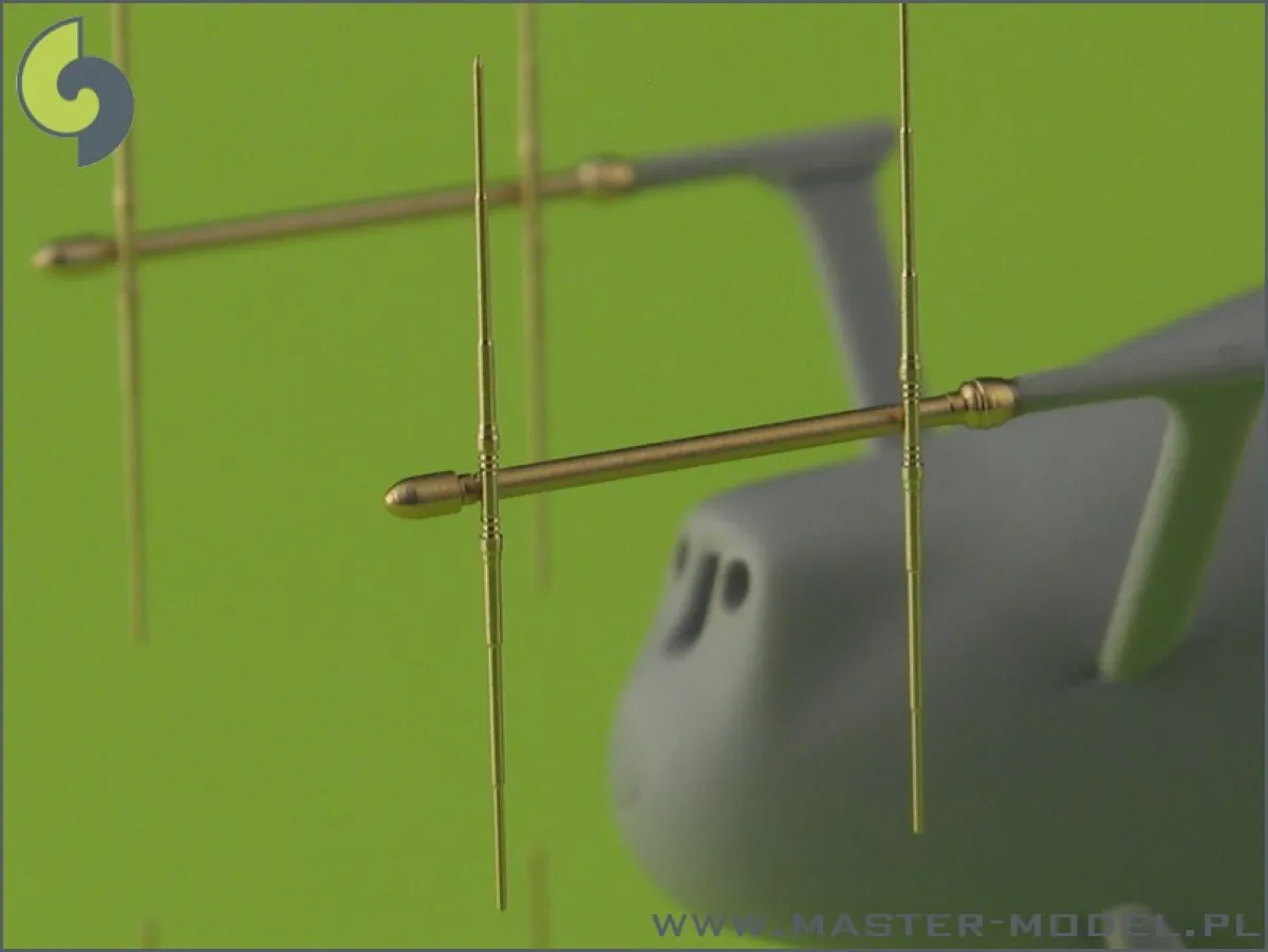
I think the point has been made...