
DK7ZB attempts to undermine G0KSC, Why?
12 Feb 2012
I must say I was disappointed to receive the Email notifying me of DK7ZB's attempts to discredit me. I had to ask the question why he felt the need to do so and these I have discussed below.
Martin presents a photo on his news page which shows a World War 2 aircraft with an array of antennas on the front. Placed in the reflector position is indeed an element which looks like an LFA loop. There are two additional parasitic in front of this loop too so perhaps it is an antenna with no reflector or is the loop indeed a reflector?
The image is not clear so I decided to do some searching around the Internet. Martin claims that this array was a part of the 'famous radar FuG200' which was designed by Prof. Scherzer on behalf of the German air force. What was very strange is searching both Google and Google images, I was not able to find another photo of this FuG200 radar antenna Martin presents. I found plenty but all had just 2 straight elements on them, I have listed them at the bottom of this article. Even some photos of exact replica models but ALL have just 2 element straight Yagis, I encourage you to do your own searching too!
Regardless of this fact of this being real antenna or not one thing is for sure, Martin's intent is to undermine my position and/or discredit me but why? Certainly it is the case that through design (both Mechanically and electromagnetically) I have undermined Martin's work but this is no personal vendetta, this is progress! He has always been of the mindset gain is all that is important and of the belief that low noise is not important on certain bands. On his 6m page he references G/T (a mean opinion score between gain and sky temperature which is a measurement to determine an antennas ability to receive signals on 144MHz up through UHF). He states 'Gain is the most critical parameter on 6M'. This quite simply shows a lack of understanding of the subject or as we say, a 'little knowledge is a dangerous thing' mixing accurate and inaccurate data and reaching a conclusion which is to say the least, mis-guided.
Obviously if he were to remove this quote about low noise being unimportant on 6m now he would undermine his own position and it would be an admission that he was wrong. Not that G/T has an influence on 6M as it certainly does not but the fact the the very low noise levels from warm earth and cold sky do not play apart at all, but 'real world' noise from the environments we live in certainly do. One of my 'recent news' items is from ZS6NK who installed a high-gain 11el M2 Yagi on one tower and compares it with a much smaller 8el LFA Yagi. Paul does not live in the city, but the differences are marked; he can hear signals on the LFA that are simply not there on the 11el.
I am quite sure that with his years in amateur antenna design he knows and appreciates the benefits of my work. Not just the LFA , the OWL, OP-DES and the bent element arrangements placed in the LFA2 (and other designs) which enhance performance. However, having free and $100 dollar design packages does somewhat limit the creativity of even the best of antennas designers.
'If a Yagi is designed correctly, there is no need to match it to 50 Ohm, it will have a direct 50Ohm feed point already'
With this 50 Ohm feed point comes:
- No power limit - Whatever your coax is rated to, you can deliver to your antenna without matching limitations
- No matching loss - Deliver QRO to a matching device and in most cases they get hot. Why? All your RF is not being radiated that's why
- Bandwidth - If designed right, A Yagi can be wide-band at any impedance, even 12.5Ohm This means stability and workability in all weathers
With G0KSC designs you get the following:
Optimisation in both Elevation and Azimuth planes to ensure lowest unwanted noise pick-up
When no consideration for pattern is given to a Yagi model, many flaws can be seen in the resulting output of the optimiser and these are plain to see in so many Yagi designs available today around the Internet. Due (in many cases) to a lack of creativity and experimentation, 'amateur' designers give too much control over the final antenna result to the optimiser and this includes boom length. The easiest route to gain is an increase in boom length and this is exactly the route the optimiser takes and why so many 28Ohm antennas have a less the perfectly falt SWR courve; they are too long ofr the number of elements they have.
Due to the power many optimisers have, boom length is increased and then swr is 're-peaked' many times. Each time this re-peaking process takes place, the boom length becomes longer and the Yagi becomes more narrow band and at the same time, more unstable in wet weather conditions. A good antenna designer would lock the boom length of the antenna and allow the optimiser to only search the space between first and last elements resulting in a much better Yagi in all respects.
It is for this reason and this reason alone that 'amateur' antenna designers believe that low impedance Yagis are always narrow-band. If a low impedance Yagi is optimised correctly (with fixed, shorter boom lengths), they can be as wide-band and as stable as any other yagi! I have proven this within the 12.5Ohm OWL Yagi (which with placement of a folded dipole becomes a direct 50Ohm fed Yagi).
An extension of this focus on gain means other important parameters suffer too. Large side lobes in both the Azimuth and Elevation planes along with what I call a 'blown rear bubble' ; the radiation pattern other than that of the main forward-facing lobe. DK7ZB quotes 'clean patterns' with huge sidelobes in bot azimuth and elevation planes on many of his antennas and from the elevation plane results, it would seem his optimisation is made in the azimuth plane when to obtain 'real' clean patterns, optimisation should only be conducted in the elevation plane. However, this is not a unique mistake, many designers fall fail of this pitful.
Take a hard look at side lobes and in both planes when selecting antennas. If there are large elevation lobes only 12/15dB down on the main forward-facing lobe, these are looking onto your surroundings, your house, those of your neighbours and basically any electrical noise generating devices there is. Modern day Yagis need to be highly suppressed in all directions other than the singular forward-facing lobe to ensure you can HEAR what can hear you. For every .1dB of forward gain given up, it is possible to achieve rear and side suppression increases of up to 1.5dB, do the math!
Many of the World's top DX'ers and EME'ers have already switched or are switching to G0KSC designed antennas. These include, G3ZSS, G3OIL, G8VR, G8BCG, G3WOS, DK1MAX, DL8YLR, DR3A, IW5DHN and soon, The Technical University of Germany DK0TU will install 16 x 8el X-POL LFA Yagis !!
Modeling the mechanical structure of the antenna, not just 'freespace wires'
Many 'amateur' antenna designers use freeware modeling packages or those just costing a few hundred US Dollars. These are fine for modeling straight wires in free space but are not able to model (accurately) the effects of the boom or other components including insulators. Out of model calculations have to be made in these instances with 'best guess' rules often applying and provided the SWR looks somewhere close, most 'amateur' designers are happy. with G0KSC antennas, the exact modeled impedance curve can be replicated in the real-world on a fully constructed antenna, how is this possible?
FEKO is an electromagnetic design package which is used for sophisticated antenna placement modeling. Within software, an antenna can be placed upon a ship, aircraft or car (as examples) and accurate performance plots seen. This modeling does not just extend to modeling booms and insulators, even the materials used within the insulator can be modeled and measured and it was here that I discovered that Polyamide insulators commonly available for ham use are NOT RF Friendly, especially on VHF/UHF frequencies.
Generally, polyamide insulators are black in colour and are used for their high UV tolerance and excellent strength. However, take a look at what 15 seconds in a microwave oven did to this Polyamide insulator:
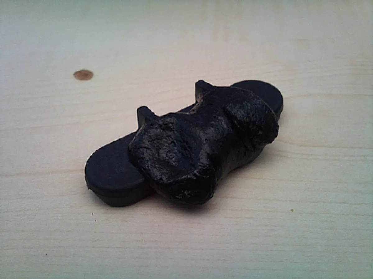
A polyamide 'antenna insulator' after just 15 second of RF in a microwave oven
So what does this this mean if you have these installed? Polyamide is 'lossy' and in QRO applications could result is a heating effect due to the carbon content. on certain bands this could result in the antenna shifting from model and therefore, the performance of your antenna may not be quite would you expected it to be. Does your antenna seem wider in bandwidth than the software model suggested??
Without question, materials without any carbon in them should be used for antenna element holders and in my opinion, should be completely insulated from the boom to ensure an 'as model' performance can be seen. While theory suggested otherwise, electrically connected (to the boom) elements (through insulator) DO shorten the elements electromagnetically and therefore correction should be applied to bring them back to model.
For correction to be 100% accurate, the amount of correction needs to vary throughout the antenna. For example, the reflector and last director have boom on only one side and therefore, the effects will be far less. Why go through all these calculations, estimate and guessing when an antenna can be replicated EXACTLY if the correct components and procedure during manufacture is used? Use Polypropylene for your insulators. It will not last as many years in high UV areas, but for me, I would rather have my antennas working correctly and replace insulators every 5/10 years and never having it work correctly for 20 years or more!
None of the above is theory, it is proven in model (thanks to FEKO) and in the real work too. Do you want antennas that work as they were designed to work or are you happy with something that is close?
Closed-loop and high impedance driven elements
One downside of low impedance Yagis is their susceptibility to pick up unwanted noise such as rain static. This is due (in part) to the high current distribution throughout the driven element in such an antenna. All G0KSC antennas (OWL with folded dipole) are high impedance and therefore current distribution through the driven element is much lower. In addition, antennas such as the LFA and OWL also have closed loop driven elements and these two attributes combined, along with the high suppressed nature of the antenna pattern mean much lower levels of (any) noise are seen.
'Bent' Elements to control impedance an performance
Earlier I made this statement: 'If a Yagi is designed correctly, there is no need to match it to 50 Ohm, it will have a direct 50Ohm feed point already'. How is this justified because lower impedance antennas show better performance in many cases right? This is true when comparing a split-dipole 50Ohm Yagi with lower impedance antennas. Where the creative part comes in, is achieving the performance of a 'would be' low impedance antenna out of one with a direct 50Ohm feed. With an LFA Yagi it is difficult to compare but not so hard with an OWL or more importantly (in this case) antennas such as the OP-DES or my new OWA2 design. Within these antennas, either the driven element or reflector is bent in order to control impedance in order that 50Ohm is seen at the feed point while at the same time, improving all performance attributes in line with what is normally associated with lower impedance antennas.
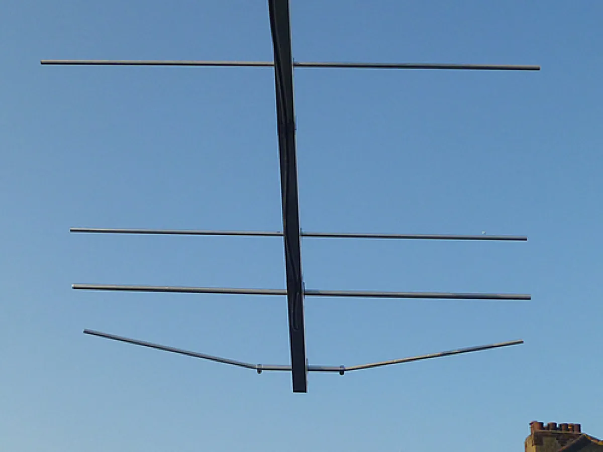
The unreleased 'OWA2' reflector which is used to maintain a 50 Ohm fed impedance whilst drastically improving F/R, bandwidth and forward gain
The problem is, bent and tapered elements cannot be modeled accurately in these $200.00 modeling packages which tend to use electromagnetic calculations engines which have not had any development for 25+ years. All G0KSC Yagis, through design, remove the requirement for any form of impedance matching and the associated problems that can be seen. Maximum radiating efficiency is also achieved with extremely high-levels of the RF entering the antenna being radiated.
Although the bent reflector is not a new idea, I first introduced this upon the LFA2 designs a year or so ago (The G3WOS has both the reflector and first director angled towards the driven loop at the tips). I am not the only antenna designer to experiment with 'shaped' reflectors. UA9TC employs a 'U' shaped reflector upon some of his VHF Yagis and this was one of the influences for the OP-DES Yagi. The OP-DES employs a similar U shape element but in this case it is within the driven element. This variation was required to ensure replication was possible as accurately as possible. When sharp bends are seen within a antenna, the radius at each corner effects the overall width the bent element will need to be. This is one reason the LFA loop is made adjustable. Firstly, adjusting the driven loop has absolute minimum impact on any performance parameters and secondly, the dipole will always need to be adjusted to 'tune-out' the additional length the driven element is given by the coax 'tails' between the coax and feed point. By combining the adjustment that the angular element will need with the driven element and keeping all other elements straight, exactly model-matching is much more likely.
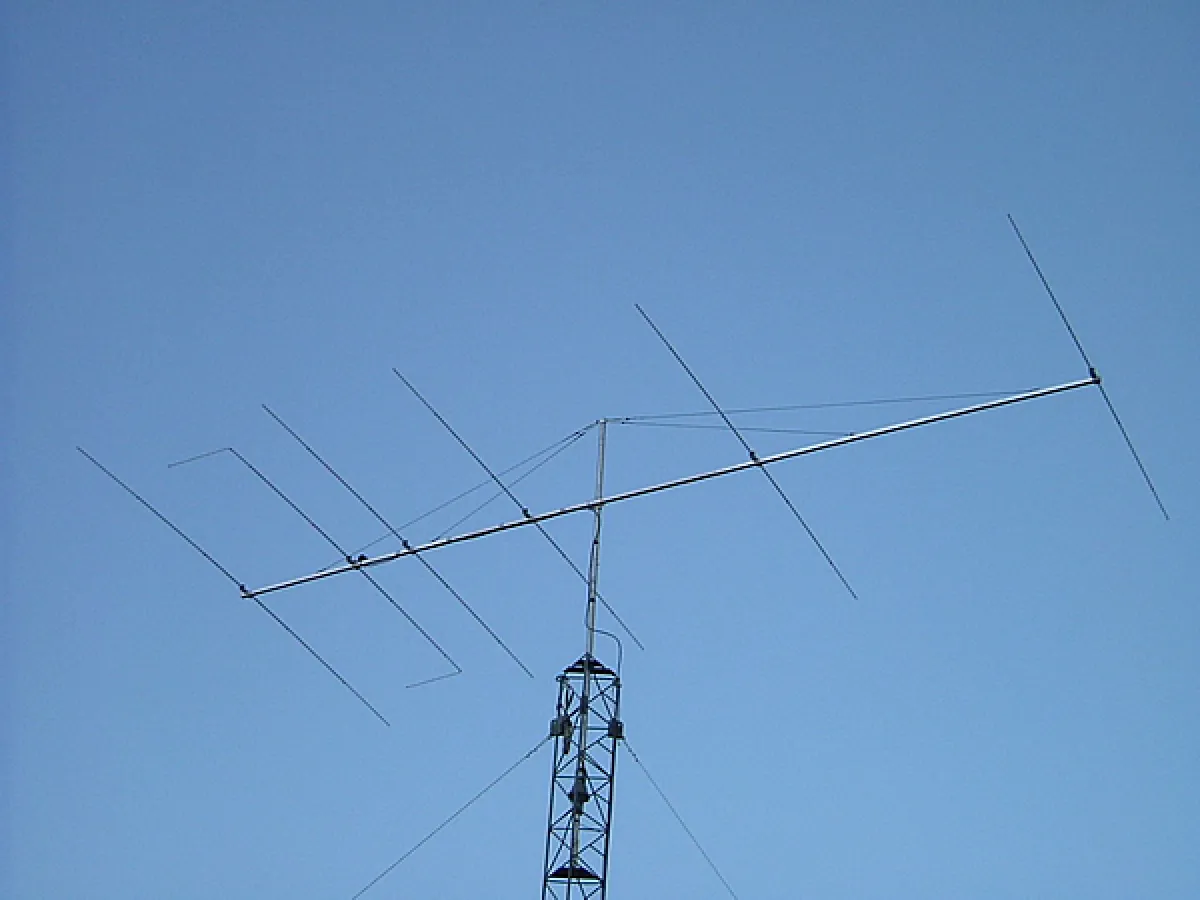
A 6el HF OP-DES with 800Khz 1.1:1 bandwidth
The LFA2 and OWA2 designs do not present the same issues as is possible with the 90 degree bends of the OP-DES elements. This is because of the much 'softer' bend the element employs although you still need to get your angles and sizing right!
An all-round package which provides the Ham with an antenna best suited to the world in which we live
HamShop in Holland installed a 4el LFA Yagi on their shop tower. One of the first comments sent to me was this 'All the modem noises and whistles have gone form ten metres!' this is not an uncommon report. Below is another from NA6XX after completing installation of his 8el 50MHz LFA:
Good morning Justin,
Thanks and have completed all the initial checkouts of the new antenna and installation. Everything seems to be working very well - now just need a bit of conditions. Checkout with a couple of the locals yesterday seem to indicate a big improvement and the RF measurements speak for themselves. I spent a lot of time making sure I got the element lengths were exactly as you specified them and the result was terrific, never made an adjustment to what you recommended. Clearly a very good match and as you said, broadband.
You might be interested to know that there was a lot of interest in what I was doing on the chat board yesterday. You are going to be making a lot of North American bound antennas I believe.
Front to back appears to be > 35 dB pretty darn good in fact maybe the best I have ever seen on any antenna. No precise front to side measurements yet but K6FV/b was +10 dB / S9 straight on and not moving the meter 90 degrees off the front. Thank you for providing an excellent design and product. Please do not hesitate to use my comments and photos anywhere you like. If you have any Hams sitting on the fence refer them to me and will be happy to provide very positive comments. BTW, another curiosity, all of my "birdies" on and around 50.110 are now gone - completely. Another big bonus.' Best 73, Chuck NA6XX
OK, it maybe frustrating to be faced with two choices, accept a better way to design Yagis has been established and these design methods undermine anything a specific designer has done in all his years. I am sure it will happen to me doing undermine all the work you have been doing other the years or secondly, look to discredit the work of the author who introduced these superior concepts and design methods.
Sadly, it looks as though he chose the latter.